Components in the Web Client
Components can be added and selected from the Components menu. Add a component by clicking the Plus button in the component table and select a component by clicking the component name. Both actions will navigate to the Component details page.
Adding a Component
Complete the following steps to add a component:
Click the Plus button on the components table, which will navigate to the component details page.
Enter the component name and choose the component type. Also choose a system (optional) and an environment. All systems are listed in the dropdown box, and by writing part of the system name, it will filter the list. It is also possible to click the select button to the left of the dropdown box. This will open a dialog where a system can be selected.
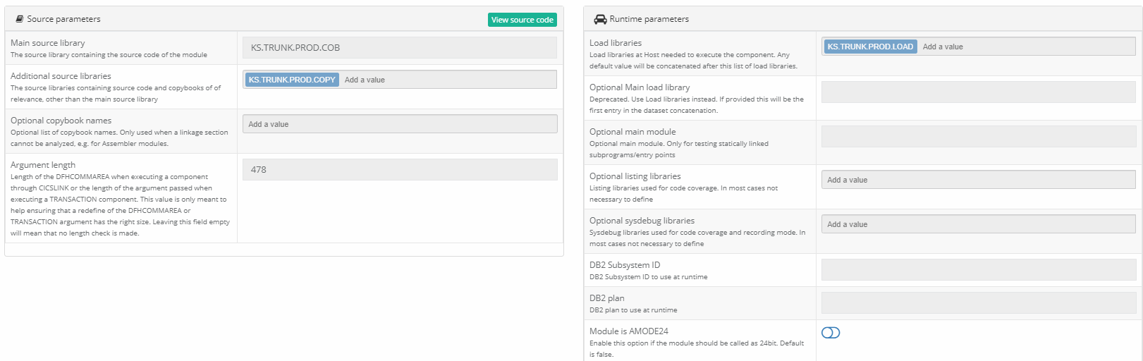
If no system matches the source and load libraries for the component, start by either creating a new System or manually entering the source and load libraries for the component. Creating a system is only a good idea when several components share the same source and runtime information. Optionally, add additional source and load libraries and change other runtime parameters. As shown in Figure Default Values, default values from the system and environment are displayed above the input fields.
When adding components that are not COBOL, you can either create the data definitions manually or write the names of the copybooks representing the data in the copybooks input field to automatically extract the data definitions.
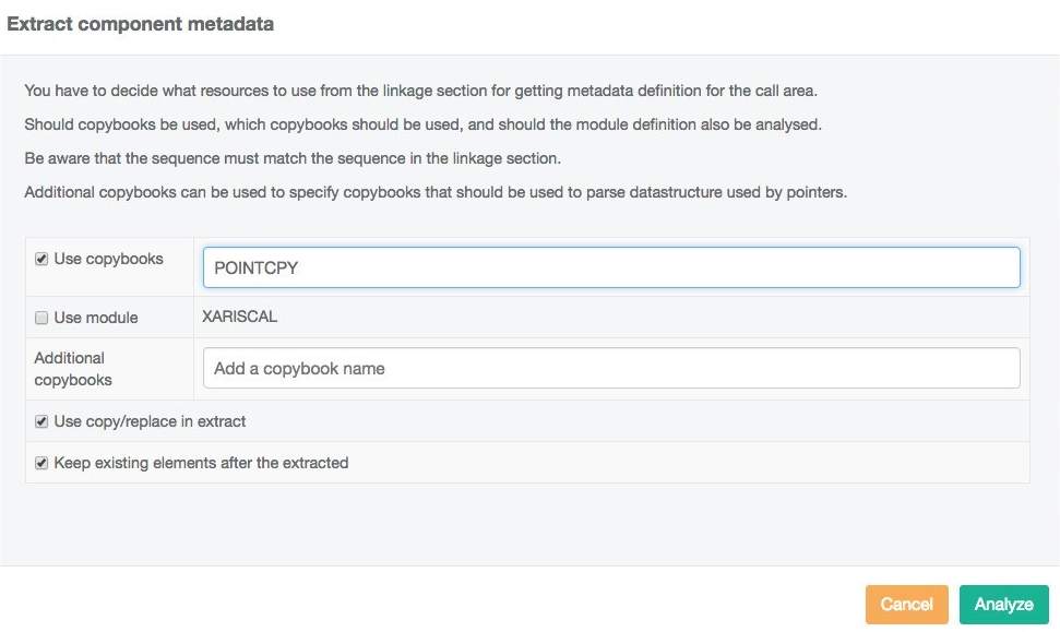
Click the Extract data definition button to extract information about data used for input/output to the program. Figure Extract Component Data Structure shows the dialog where you can choose to analyze the linkage section of the program module or to analyze the copybooks listed in the copybook input field. Choosing the module works only for COBOL programs while the copybook option works for all types of programs. You can also choose to use copy/replace in the extraction and to keep the existing elements for the component. This can be valuable when you have made manual changes to the existing elements.
Extract Component Data Structure
Optionally change the data definition manually. If the data contains pointers, select the data item to which the pointer refers and optionally choose to not include the data area, itself, as an argument in the parameter list used to call the program.
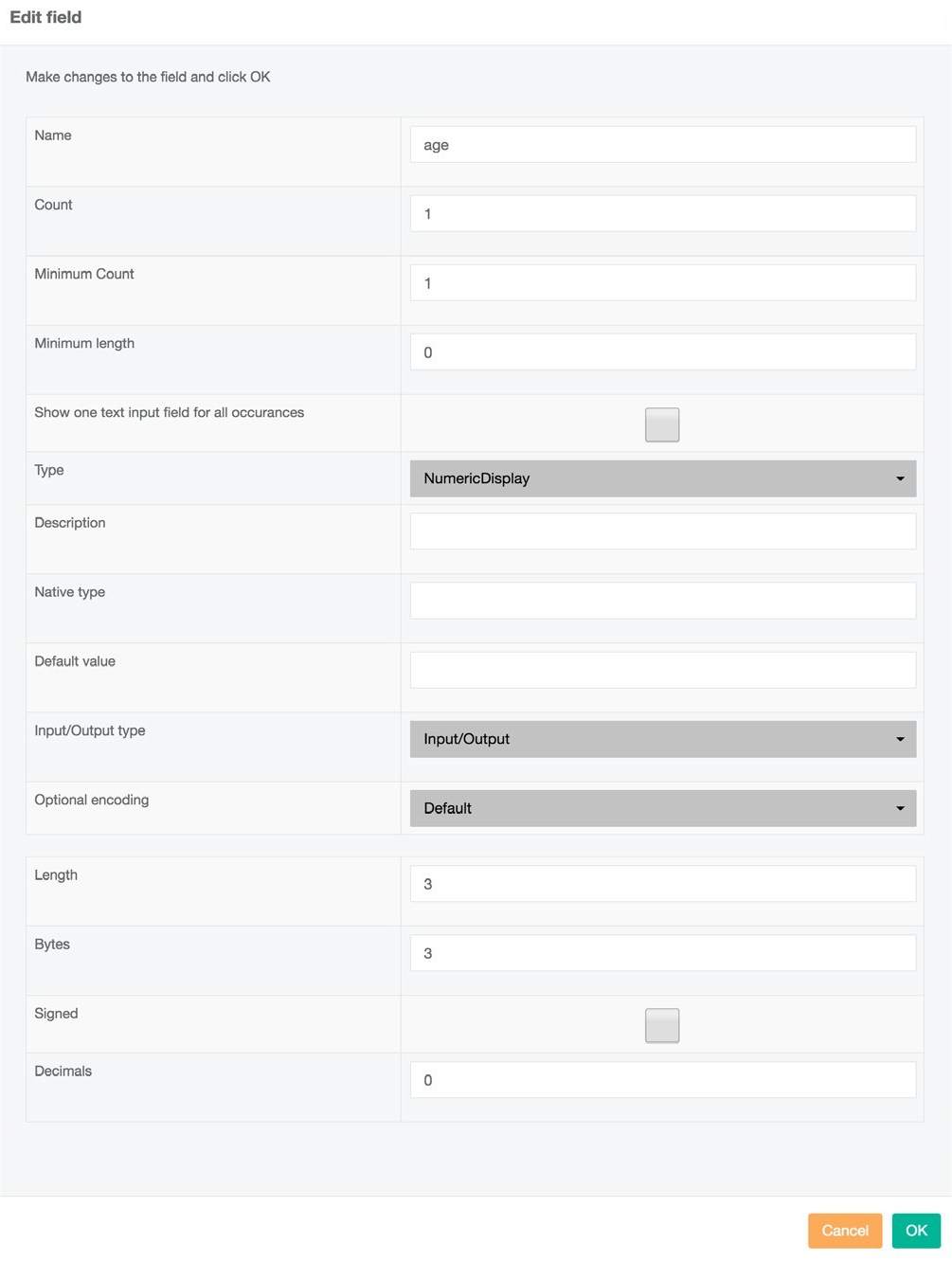
Optionally add a description, change the encoding, and modify other settings for a field by clicking the edit button next to a field in the data structure. A dialog appears as illustrated in Edit Field Dialog.
Optionally enable the Allow execute without credentials if you want to create graphical skins that should be used without logging into Non-virtualized Test (Functional Test). Enabling this option will require you to enter a valid host userid and password that will be used for authorization when the component is executed through a skin. The password will be encrypted and saved in the database.
Click Create to create the component.
Using Pointer Fields
If a field is a pointer, you have to choose another structure that maps the storage area that it will reference. This structure must be a top-level element in the data structures list. You can define the structure manually, or you can use the Extract data definition feature to add it to the data structures list. Typically, this element is not an argument in the parameter list used to call the program.
Complete the following steps to add a data structure for a pointer to a Component and to exclude the data structure from the parameter list used to call the program:
Select the component and click the Edit button
At the Data structure section click Extract data definition. In the Extract dialog, choose Use copybooks and specify the name of the copybook. Use option Keep existing elements after the extract so existing elements will not be overwritten.
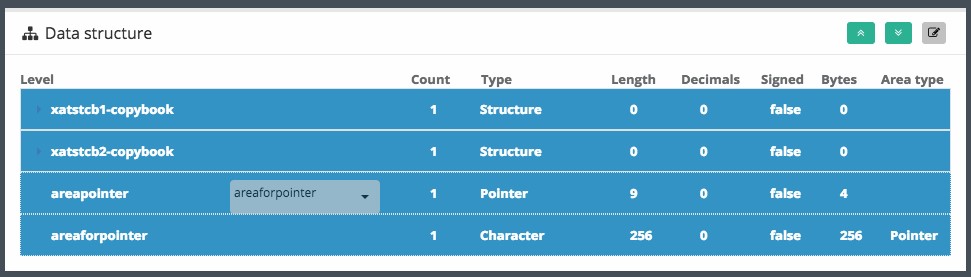
At the newly added data element, click the Toggle Edit Mode button to the right and select the Area type to be Pointer area. This will exclude the data structure from the parameter list used to call the program.
For the pointer element, select the name of the newly added data structure in the dropdown next to the pointer element name. The name can also be written as text if you click the Edit button for the field.
When executing a component, it is possible for the concrete test Scenario/execution to override the pointer reference. It is also possible to specify a null value. Write $NULL to specify this.
Memory allocation
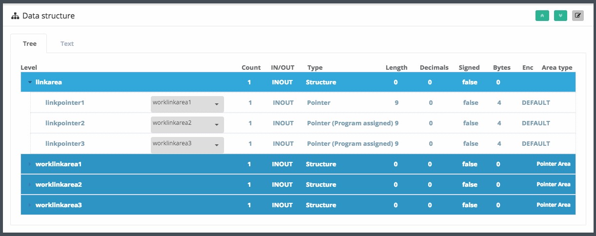
By default, allocation of the storage area referenced by a pointer is done by Non-virtualized Test (Functional Test) prior to calling the program that is the target of the test. If the target program, itself, obtains the storage area referenced by a pointer, click the Edit button and check the option Program assigned memory.
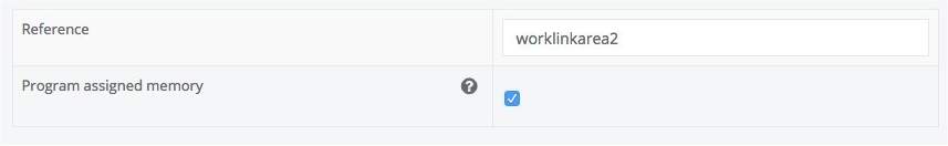
This will be indicated in the data structure list, afterwards. Below is an example using the demo program XADPTRS1, which has two program assigned pointers and one Non-virtualized Test assigned pointer.
Using CICS COMMAREA and EIB
CICS programs may use COMMAREA for input/output data. When call type CICSCALL or CICSLINK is chosen, the first top-level element in the data structures list represents COMMAREA, which is the actual second argument in the program's parameter list when conventional CICS linkage is used. With CICSCALL, additional parameter list arguments can be specified, following COMMAREA, in the order in which they appear in a COBOL USING list, for example. With CICSLINK, additional parameter list arguments, following COMMAREA, are not used. In the case in which a program does not reference the COMMAREA passed to it, a top-level element for it should still be included in the data structures list, at least as a one-character field.
With conventional CICS linkage, the first argument in the program's parameter list is the CICS EXEC interface block (EIB). Total Test supplies a default EIB to be this first parameter when calling the target program, even though it is not included in the component's data structures list when using call type CICSCALL or CICSLINK. If specific EIB input data must be supplied, for example, to pass the expected length of COMMAREA, then use call type CALL, instead. Create the EIB data structure by extracting it from copybook dfheiblk, and add it as the first top-level item in the data structures list, followed by COMMAREA as the second.
Using CICS Containers, Temporary Storage and TWA
When a CICS program is called by a CICS LINK command, it is possible to set up data to be transferred using CICS containers, CICS temporary storage, TWA, or a combination of these. Indicate this for a top-level element in the data structures list by using its Area type property. A section appears below the data structures list with an entry for each top-level element that has been associated with a CICS area type. As an example, let's look at the Non-virtualized Test (Functional Test) demo program XADCICC3. It has four top-level elements, two are BIT containers and two are CICS main temporary storage queues. The properties defined for these are as follows:
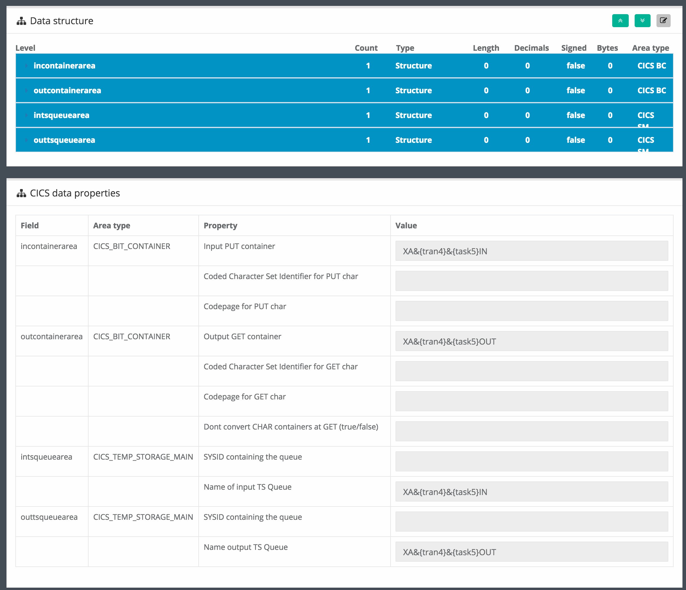
In this example, only the names of the input/output containers and TS queues are set. When required, CCSID, codepage, and SYSID can also be specified. The CICS channel name is set at the component level, under runtime parameters. Container names and TS queue names can contain substitution variables for CICS task number, user ID, and transaction ID. The variable's syntax is &{<symbol>}, where <symbol> is any of the following:
taskn : CICS task number, 4 bytes packed decimal
task4 : CICS task number, last 4 characters
task5 : CICS task number, last 5 characters
task6 : CICS task number, last 6 characters
task7 : CICS task number, last 7 characters
task8 : CICS task number, 8 characters
user1 : CICS user ID, first character
user2 : CICS user ID, first 2 characters
user3 : CICS user ID, first 3 characters
user4 : CICS user ID, first 4 characters
user5 : CICS user ID, first 5 characters
user6 : CICS user ID, first 6 characters
user7 : CICS user ID, first 7 characters
user8 : CICS user ID, 8 characters
tran1 : CICS transaction ID, first character
tran2 : CICS transaction ID, first 2 characters
tran3 : CICS transaction ID, first 3 characters
tran4 : CICS transaction ID, 4 characters
Using Show One Field for All Occurrences
Many components have filler fields and other fields of typically one character/byte with a large number of occurrences. Such fields will be represented with the same number of input text fields as the occurrence/count number which can be annoying. It is possible to represent such fields or the overlying structure as just one field to the user. The input value entered by the user will then be divided into separate data entities and distributed to the individual field occurrences.
We will illustrate the feature with the XAPGMTST demo program. In the first top-level element for XAPGMTST we will change the week-count structure. The week-count structure contains a wcount field with a count/occurrence of 4. The wcount field is a NumericBinary of length 4. We will set the week-count structure as Show as one input field. This will change the user interface from presenting 4 input fields for wcount under week-count to only present one input field for week-count with the length of 16.
Complete the following steps to setup using one field for a structure
Choose the XAPGMTST component and click the Edit button.
Click the Edit button next to the week-count field.
Select the Show one text input field for all occurrences option and click OK.
Click Update to update the component definition.
Goto the execute page to see the new UI presentation of data. Below we illustrate the difference. First image shows default presentation:
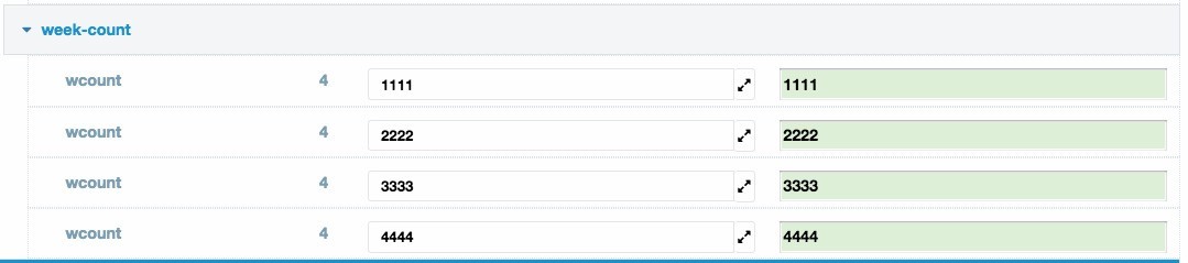
and second image shows using one input field:
It is also possible to set the option at the wcount field itself instead of the parent structure week-count. When the wcount field is set to be represented as one field, the presentation of data will look like the image below.

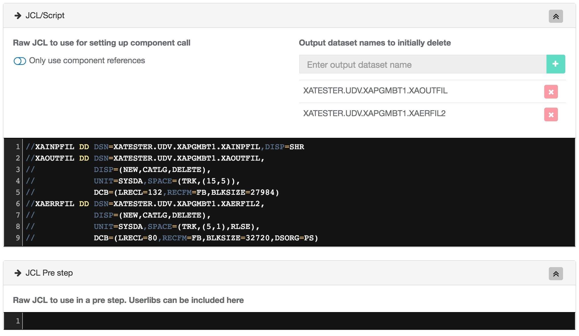
JCL/Script and JCL Pre Step
It is possible to add JCL to the component definition. The JCL will be appended to the JCL that is generated when the component is being executed. More precisely it will be used in the step that is executing the component. The JCL can be defined in the JCL/Script section and each line must be maximum 72 characters.
When the toggle Only use component reference is on, JCL from the System will not be used. Default is to use both the System JCL and the component JCL.
In the JCL Pre step section you can define JCL that will be used in a step before the step that will execute the component. It is possible to use JCLLIB in the JCL. Non-virtualized Test (Functional Test) will then setup the JCLLIB in the top of the JCL.
Modifying a Component
Select a component from the component table and then click the Toggle Edit Mode button. This will set the page in edit state. Change any options as described above and finally click Update. The component can also be deleted, but only if it is not used by any skins, stubs or scripts.
As a utility feature, it is possible to open the source code for the component directly in the browser when the source is available as a dataset. Just click the View source code button. In the source code, you can double-click on a copybook located in the linkage section and it will also open in the editor as an additional tab. The source editor has settings where line numbers, theme and maximum number of bytes to retrieve can be changed.